|
 |
 |
 |
 |
 |
 |
 |
 |
 |
 |
 |
 |
 |
 |
 |
 |
 |
2910 Model Number, 2 Wire 4-20 mA RTD Transmitter |
 |
 |
| |
 |
 |
 |
Minimum Temperature, 4 mA Zero Temperature |
 |
| |
 |
 |
 |
Maximum Temperature, 20 mA Span Temperature |
 |
| |
 |
 |
 |
Temperature (°C or °F) |
 |
| |
 |
 |
 |
CONNECTION HEAD |
 |
D
K |
Without Connection Head
Head DIN B Cast Aluminum |
|
 |
 |
 |
 |
 |
 |
 |
 |
 |
|
 |
 |
 |
 |
 |
 |
 |
 |
|
- |
|
- |
|
- |
|
- |
|
- |
Typical write-up for 2910 |
 |
 |
 |
 |
 |
 |
 |
 |
 |
 |
 |
 |
 |
 |
 |
 |
 |
 |
 |
 |
 |
 |
 |
 |
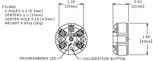
Calibrate with a small (3 mm) diameter screwdriver
and an RTD simulator (or decade resistor).
1. Simulate the RTD resistance at the 4 mA temperature.
2. Press the programming switch (using the small screwdriver) until the RED programming LED flashes.
3. Simulate the RTD resistance at the 20 mA temperature.
4. Press the programming switch (using the small screwdriver) momentarily and the RED programming LED flashes quickly. |
|
 |
 |
|


