|
The primary calibration function of heat flow sensors is performed using an adiabatic calorimeter. The calibration sensor is carefully mounted on a copper calorimeter slug and a flat black coating is applied to all sensor surfaces for uniform absorptance. The calorimeter slug is then exposed to a radiant heat source on one surface at various power levels. A schematic of radiant heat flux facility is shown in Figure 3.
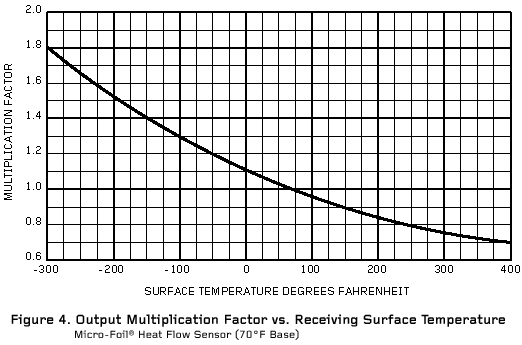
For production calibration, a comparison calibration setup is used whereby a test sensor is compared in heat flow series conduction with a primary standard sensor that has been radiation calibrated as described above. The production calibration is performed at 70°F and temperature correction data is provided over the operating temperature range. A typical temperature correction chart for Micro-Foil® heat flow sensors with a Kapton® thermal barrier is shown in Figure 4.
Both radiation and conduction were used in the methods of calibrations described above. A recent NIST study has confirmed that the resultes apply accurately in convection heat flow as well. RdF’s thin sensor results in the reference were much better than results on thick sensors by others.
Because of their extremely thin construction, Micro-Foil® sensors feature true isothermal properties where thermal losses are kept to a minimum and highly accurate readings are obtainable. The sensors provide self-generated millivolt or microvolt outputs, which are proportional to the heat flow through the sensor thickness. Catalog choices of sensitivity are offered by changing the thickness of the thermal barrier and/or the number of thermopile junctions within the sensor.
Typical specifications are as follows:
Heat flow range: Up to 30,000 Btu–ft–-2-h–1.
For heat flow above 3000 Btu–ft–-2-h–1, special installation procedures or insturment assemblies with heat sinking or water cooling are required for extended operation. (New water cooled model 27650 is a laboratory grade instrument continuously useable to over 100,000 Btu–ft–-2-h–1 with 2x overrange capability, fast 0.02 second response time and a permanently black sensing surface.) |
| |
| Typical sensitivity: 0.07 to 40 MV-Btu–ft–-2-sec–1 |
| |
Typical response time: 0.02 to 0.50 secs.
(function of matrix material thickness) |
| |
Operating temperature range: -300 to +500°F
(determined by matrix material and assembly) |
| |
Typical thermal impedance: 0.003 to 0.015 Btu–ft–-2-h–1
(determined by properties of matrix material and thickness) |
| |
| Typical thermal capacitance: 0.01 to 0.05 Btu–ft–-2-°F–1 |
The use of the calibration procedures described provides sensors with a typical absolute calibration accuracy of 3 to 5%. Reproducibility is, however, in the order of 1%. The construction of the sensor provides infinite resolution over the heat flow range.

|


