| |
 |
 |
 |
 |
 |
 |
 |
 |
 |
 |
 |
 |
 |
|
|
 |
 |
 |
 |
 |
23A
23B |
 |
1/4" Dia. straight probe, 316 stainless steel
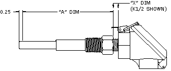
1/4" Dia. probe with rigid 1/2 - 14 NPT stainless hex fitting |
 |
 |
 |
 |
 |
 |
RTD RESISTANCE SPECIFICATIONS (Ohms @ 0°C) |
 |
 |
T01
T10
H10 |
 |
100 ± 0.12 (a = 0.00385 Ω/Ω/°C) thin film, IEC751
1000 ± 1.2 (a = 0.00385 Ω/Ω/°C) thin film, IEC751
1000 ± 1.2 (a = 0.00375 Ω/Ω/°C) thin film, Industrial |
 |
 |
 |
 |
 |
CONNECTION HEAD – 23B Only (see table)
|
 |
 |
 |
 |
 |
 |
PROBE LENGTH (specify “L” in inches) (see drawings) |
 |
 |
 |
 |
 |
 |
LEAD WIRE CONFIGURATION |
 |
A
B
C
X3
X4 |
 |
Single element, 2 wires any length
Single element, 3 wires 36" or under in length
Single element, 4 wires 36" or under in length
Single element, 3 wire cable over 36"
Single element, 4 wire cable over 36" |
 |
 |
 |
 |
 |
ARMOR LENGTH (21A only)
Specify “X” in inches (ie. A0 = no armor, A60 = 60 inches)
(Single element only) |
 |
 |
 |
 |
 |
 |
 |
LEAD LENGTH (specify in inches)
(12" standard on 23A)
(4" standard on 23B) |
 |
 |
 |
 |
 |
 |
 |
 |
 |
 |
 |
 |
 |
 |
 |
 |
 |
 |
 |
|
– |
|
 |
– |
|
|
– |
|
– |
|
– |
|
– |
Typical write-up for 23A |
 |
 |
|
– |
|
– |
|
– |
|
– |
|
– |
|
– |
|
– |
Typical write-up for 23B |
 |
 |
 |
 |
 |
 |
 |
 |
 |
 |
 |
 |
 |
 |
 |
 |
 |
 |
 |
 |
 |

Type 23D – Spring Loaded Probe Assembly
|
 |
 |
 |
 |
 |
 |
 |
 |
 |
 |
 |
 |
 |
 |
 |
 |
 |
 |
 |
 |
 |
 |
23D |
1/4" Dia. Spring Loaded Stainless Hex Probe Assembly |
 |
 |
|
 |
 |
 |
RTD RESISTANCE SPECIFICATION (Ohms @ 0°C) |
 |
T01
T10
H10
|
100 ± 0.12 (a = 0.00385 Ω/Ω/°C) thin film, IEC751
1000 ± 1.2 (a = 0.00385 Ω/Ω/°C) thin film, IEC751
1000 ± 1.2 (a = 0.00375 Ω/Ω/°C) thin film, Industrial |
 |
 |
 |
 |
 |
PROBE LENGTH IN THERMOWELL
( “A” bore depth in inches, see drawing) |
 |
 |
 |
 |
 |
 |
PROBE LAG HARDWARE 1/2 x 1/2 NPT |
 |
A
*
GX
HX
JX
KX |
Hex nipple is 3/4" long stainless*, specify as “A” (standard)
Other stainlesss hardware, see Data Sheet R-21
(Coupling/nipple extension), black iron,
specify x = min. 3" plus 1" increments
(Union/nipple extension), black iron,
specify x = min. 3" plus 1" increments
(Close nipple, galvanized unsealed parting coupling, nipple extension), black iron,
specify x = minimum 1 1/2" + 1" increments (shortest “union”)
(Straight nipple), black iron, specify x = 1/8", 1/2", 1", + 1" increments (CREDIT) |
 |
 |
 |
 |
 |
CONNECTION HEAD (see table below) |
 |
 |
 |
 |
 |
 |
LEAD WIRE CONFIGURATION |
 |
A
B
C
X3
X4 |
Single element, 2 wires any length
Single element, 3 wires 36" or under in length
Single element, 4 wires 36" or under in length
Single element, 3 wire cable over 36"
Single element, 4 wire cable over 36" |
 |
 |
 |
 |
 |
LEAD LENGTH (specify in inches)
(4" standard) |
 |
 |
 |
 |
 |
 |
 |
 |
 |
 |
 |
 |
 |
 |
 |
 |
 |
 |
|
– |
|
– |
|
– |
|
– |
|
– |
|
– |
|
– |
Typical write-up for 23D |
 |
 |
 |
 |
 |
 |
 |
 |
 |
 |
 |
 |
 |
 |
 |
 |
 |
 |
 |
 |
 |

 |
 |
|
 |
NEMA 4 w/gasket |
 |
Conduit |
 |
Max. Temp |
 |
 |
 |
 |
 |
 |
| A |
Small cast aluminum head |
1/2 NPT |
125°C |
 |
 |
 |
 |
| C |
Cast Iron head |
3/4 NPT |
260°C |
 |
 |
 |
 |
| D |
For no connection head specify “D” |
- |
- |
 |
 |
 |
 |
| E |
Large cast aluminum head |
3/4 NPT |
260°C |
 |
 |
 |
 |
| F |
Economy conduit body |
1/2 NPT |
125°C |
 |
 |
 |
 |
| I |
Hinged plastic |
3/4 NPT |
125°C |
 |
 |
 |
 |
| J |
Hinged cast aluminum |
3/4 NPT |
125°C |
 |
 |
 |
 |
| K |
Din B cast aluminum |
1/2 NPT |
100°C |
 |
 |
 |
 |
| S |
Other (please specify when ordering) |
- |
- |
 |
 |
 |
 |
| T |
Transmitter, specify or supply w/head |
- |
- |
 |
 |
 |
 |
|


