| |
When discussing RTDs, several specifications must be considered:
 Wiring configuration (2, 3 or 4-wire) Wiring configuration (2, 3 or 4-wire)
Self-heating
Accuracy
Stability
Repeatability
Response time
 Wiring Configuration Wiring Configuration
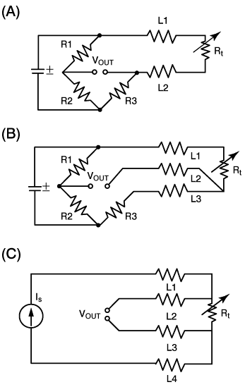
Serious lead-wire resistance errors can occur when using a two-wire RTD (see Fig. 3A), especially in a 100Ω sensor.
In a two-wire circuit, a current is passed through the sensor. As the temperature of the sensor increases, the resistance increases. This increase in resistance will be detected by an increase in the voltage (V = I•R). The actual resistance causing the voltage increase is the total resistance of the sensor and the resistance introduced by the lead wires. As long as the lead wire resistance remains constant, it can be offset and not affect the temperature measurement. The wire resistance will change with temperature, however, so as the ambient conditions change, the wire resistance will also change, introducing errors. If the wire is very long, this source of error could be significant. Two-wire RTDs are typically used only with very short lead wires, or with a 1000Ω element.
 |
 |
|
Figure 3. Lead wires have resistance that is a function of the material used, wire size, and lead length. This resistance can add to the measured RTD resistance, and improper wire compensation can result in significant errors.
The common configurations of RTDs are two (A), three (B) or four wires (C). |
|
|
In a 3-wire RTD (see Fig. 3B), there are three leads coming from the RTD instead of two. L1 and L3 carry the measuring current, while L2 acts only as a potential lead. Ideally, the resistances of L1 and L3 are perfectly matched and therefore canceled. The resistance in R3 is equal to the resistance of the sensor Rt at a given temperature—usually the begining of the temperature range. At this point, V out = zero. As the temperature of the sensor increases, the resistance of the sensor increases, causing the resistance to be out of balance and indicated at V out. Resistances L1 and L3 in leads up to tens of feet long usually match well enough for 100 Ω three-wire RTDs. The worst case is resistance offset equal to 10% of single-lead resistance.
The optimum form of connection for RTDs is a four-wire circuit (see Fig. 3C). It removes the error caused by mismatched resistance of the lead wires. A constant current is passed through L1 and L4; L2 and L3 measure the voltage drop across the RTD. With a constant current, the voltage is strictly a function of the resistance and a true measurement is achieved. This design is slightly more expensive than two or three-wire configurations, but is the best choice when a high degree of accuracy is required.
Self-Heating
To measure resistance, it is necessary to pass a current through the RTD. The resultant voltage drop across the resistor heats the device in an effect known as the I2R, or Joule heating. The sensor's indicated temperature is therefore slightly higher than the actual temperature. The amount of self-heating also depends heavily on the medium in which the RTD is immersed. An RTD can self-heat up to 100x higher in still air than in moving water, so self-heating specifications are just a conservative guide.
Accuracy/Interchangeability, Stability & Repeatability
These terms are often confused, but it is important to understand the difference.
 |
Accuracy/Interchangeability
|
| |
|
| |
IEC standard 751 sets two tolerance classes for the interchangeability of platinum RTDs: Class A and Class B:
Class A: Dt °C = ± ( 0.15 + 0.002 • | t | )
Class B: Dt °C = ± ( 0.30 + 0.005 • | t | )
where:
| t | = absolute value of temperature in °C
Class A applies to temperatures from –200°C to 650°C, and only for RTDs with three or four-wire configurations. Class B covers the entire range from –200°C to 850°C.
A major advantage of platinum RTDs is that calibration at as few as two temperatures offers accuracy, preserved by high stability, much tighter than even Class A interchangeability. No other temperature sensor offers specifications for stability (see following) that will preserve laboratory accuracy embedded in calibrations over long time periods and wide temperature ranges and every configuration. Primary Standard Resistance Temperature Sensors (SPRTS) are platinum for good reason.
|
| |
|
|
Stability
|
| |
|
| |
This is the sensor's ability to maintain a consistent output when a constant input is applied. Physical or thermal shocks can cause small, one-time shifts. The material that the platinum is adhered to, when wound on a mandrel or deposited on a substrate, can expand and contract differentially to cause strain incorporated in normal performance but not cause shifts. Stability limits conservatively specified by RdF are typically 0.05°C/yr in wide temperature ranges or 0.05°C/5yrs in medium ranges. |
| |
|
|
Repeatability
|
| |
|
| |
Repeatability is the sensor’s ability to give the same output or reading under repeated identical conditions. In platinum RTDs, cycle to cycle differences normally can’t be measured and are considered lumped into stability specifications.
Absolute accuracy is not necessary in most applications. The focus should be on the stability and repeatability of the sensor. If an RTD in a 100.00°C bath consistently reads 100.06°C, the electronics can easily compensate for this error. The stability of platinum RTDs is exceptional, with most experiencing drift ratesf <0.05°C over a five-year period.
|
| |
|
|
Response Time
|
| |
|
| |
Response time is the sensor’s ability to react to a change in temperature, and depends on the sensor's thermal mass and heat transfer from the material being tested. For instance, an RTD probe in a thermowell will react much more slowly than the same sensor immersed directly into a fluid.
The sensor in a solidly bonded internal assembly responds twice as fast as one with a single loose interface in the same assembly.
Surface RTDs respond quickly to surface temperature change. RTD specifications will list the sensor's time constant, which is the time it takes for an RTD to respond to a step change in temperature and come to 63% of its final equilibrium value.
Probe response times are measured in water flowing at 3ft/sec (1m/s) and in air flowing at 10ft/sec (3m/s). This gives a useful comparison of RTD probe configurations.
Relationships useful for extrapolating response times, t, within the same probe construction and the same flow characteristics are as follows.
If cylindrical probe diameter, d, is changed for the same fluid mass flow across the probe:
| t µ d1.5 or t2/t1= (d2/d1)1.5 |
(8) |
If fluid mass flow, m, is changed for the same probe diameter:
| t µ 1/m0.5 or t2/t1= (m1/ m2)0.5 |
(9) |
|
| |
|
| |
|
|