| DATA SHEET T-F Surface Thermocouples | |
 |
 |
|
THE ALL-TIME PERFORMANCE STANDARD
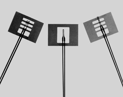
Ideal Thermal Contact, Fast Response Thin foil, 0.0002" and 0.0005" thick, gives extremely low thermal inertia plus maximum thermal coupling to the mounting surface. Thermocouple grade materials are used throughout the foil and leads for accuracy. Errors caused by thermal conduction between junction and leads are negligible, since the length to thickness ratio of the foil junction portion ranges from 500:1 to 2000:1. Micro-Foil® butt bonding produces thermocouples with no increase in thickness or mass at the junction. Location of the junction is definite and concise, essentially a short line, not spread out. Butt bonded foil is an intimate thermal layer at the sensing surface. |
 |
||
|
APPLICATIONS: BARE FOIL WITH CARRIER (SKETCH A) For handling ease, a temporary carrier of polyimide film supports the bare foil. The Kapton® polyimide film is tough, flexible, and dimensionally stable. It is exceptionally heat resistant and inert. Portions of the carrier can be easily cut away with a scissors or knife. The foil sensor is fastened to the polyimide film carrier, at one point only, by a thermoplastic adhesive. During installation, the carrier is normally removed. However, all or part of the polyimide carrier, due to its heat resistance and inertness, may be left in the sensor installation with little or no loss in thermocouple performance. The carrier will withstand the prolonged heating at 600° to 750°F required for the curing of most ceramic cements. RdF bare foil surface thermocouples (Sketch A) are intended primarily for application with ceramic cements. The free foil thermocouple can be easily brushed into a thin second layer of cement, following application and drying of a thin insulating layer, to produce an ungrounded junction. To remove the carrier film during installation, peel back carefully or touch the attachment point with a hot soldering iron. Installation can be made directly to nonconductive materials with any of a variety of cements. Grounded junction may be made on conductive materials if desired. Grounded junctions have response times between 1 and 5 milliseconds. Consult RdF for other bare foil models with additional carrier bars designed to stabilize the foil position for plasma sprayed oxide application. LAMINATED FOIL ASSEMBLIES RdF laminated foil surface thermocouples are prefabricated and ready to use. They have the foil sensor embedded in a paper-thin laminate of glass-reinforced, high-temperature polymer and are intended for ungrounded surface application by adhesive bonding. Thin and flexible, they can be bonded to flat or curved surfaces. The polymer used in the laminate has been selected for maximum heat resistance and electrical properties. Glass-reinforced polyimide polymer and Kapton® polyimide film outer layers make it possible to obtain a life of many thousands of hours at 500°F, hundreds of hours at 600°F, tens of hours at 700°F, and short time excursions to 800°F. RdF laminated foil surface thermocouples (Sketches D, E, and F), are designed for easy installation with conventional reactive or pressure-sensitive adhesives. Select adhesive to suit the maximum expected operating temperature. Avoid solvent release adhesives that may not produce a void free bond. Epoxy adhesives, especially those suitable for continuous use at 500°F, are generally satisfactory. The design shown in Sketch D is made for minimum mass and fastest response (less than 10 milliseconds for 63%, ungrounded). The designs shown in Sketches E and F feature rugged fiberglass insulated lead wires suitable for the maximum use temperatures. |
| Sketch No. |
RdF Material Part No. |
Thermocouple & Lead Material |
Foil Thickness |
Lead Dimensions |
Temperature Range* |
|||||||
| A | 20100-1 20100-2 |
Chromel/Alumel Type K |
0.0002 0.0005 |
0.001 x 0.03 0.002 x 0.03 |
–320 to +1500°F | |||||||
| 20101-1 20101-2 |
Chromel/Constantan Type E |
0.0002 0.0005 |
0.001 x 0.03 0.002 x 0.03 |
–320 to +1200°F | ||||||||
| 20102-1 20102-2 |
Copper/Constantan Type T |
0.0002 0.0005 |
0.001 x 0.03 0.002 x 0.03 |
–320 to +700°F | ||||||||
| D | 20109 | Chromel/Alumel Type K |
0.0002 | 0.001 x 0.03 | –320 to +500°F Continuous +600°F: 600 Hours +700°F: 10 Hours |
|||||||
| 20110 | Chromel/Constantan Type E |
|||||||||||
| 20111 | Copper/Constantan Type T |
|||||||||||
| E | 20112-(L) | Chromel/Alumel Type K |
0.0005 | #30 AWG (0.010 diameter) Fiberglass Insulated Fiberglass Overbraid |
–320 to +500°F Continuous +600°F: 600 Hours +700°F: 10 Hours |
|||||||
| 20113-(L) | Chromel/Constantan Type E |
|||||||||||
| 20114-(L) | Copper/Constantan Type T |
|||||||||||
| F | 20115-(L) | Chromel/Alumel Type K |
0.0002 | #36 AWG (0.005 diameter) Fiberglass Insulated Fiberglass Overbraid |
–320 to +500°F Continuous +600°F: 600 Hours +700°F: 10 Hours |
|||||||
| 20116-(L) | Chromel/Constantan Type E |
|||||||||||
| 20117-(L) | Copper/Constantan Type T |
|||||||||||
 |
||
800.445.8367 • 603.882.5195 • fax 603.882.6925 • www.rdfcorp.com |
||