|
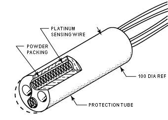
threaded mandrel (or the insulated inner wall of the sensor assembly). Figure 3 shows a typical coiled element manufactured by RdF.
Whatever strain-free method is used, it generally provides a sensor with a higher temperature coefficient and better stability. Of all typical designs, the RdF design, shown here, is the most rugged. All laboratory standard platinum resistance thermometers (SPRTs) are specialized strain-free designs.
 |
| Figure 3. The coiled element sensor, made by inserting the helical sensing wires into a packed powder-filled insulating mandrel, provides a strain-free sensing element. |
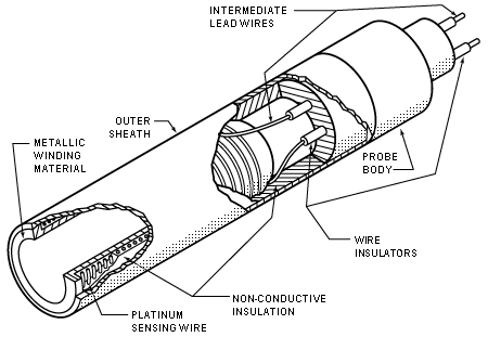
The last style, the hollow annulus sensing element, uses an open-ended metal winding mandrel which increases fluid contact and lowers thermal mass to provide a faster time response. In a typical design, shown in Figure 4, the winding mandrel — fabricated from weldable corrosion resistant metal — is machined to eliminate the internal mass. The winding area is coated with an insulating material and the sensing wire-wound to a predetermined value. The element is then covered with a coating of insulating material. This sensor has a thin external metal sheath welded over the winding area when it is used with no additional housing.
 |
| Figure 4. The hollow annulus-type element is made by winding platinum sensing wire around a hollow corrosion-resistant metal mandrel. The entire unit is coated with an inuslating material. |
This element has the advantages of being completely sealed and having an extremely fast time response, but it is the most expensive of the four types. The large winding diameter enables high resistance sensors to perform optimally in cryogenic fluid applications.
Each of the four sensing elements discussed has advantages and disadvantages. Before purchasing an RTD assembly, it is advisable to know what type of element the manufacturer is intending to provide and its limitations.
 Internal Construction Internal Construction |
The sensing elements are very seldom used by themselves and must be packaged to interface with existing hardware and withstand service conditions. Due to thousands of applications for RTDs, there are an infinite number of RTD assembly |
|
configurations. This section gives a brief description of the most simple and commonly used constructions.
The assembly process begins with connections between the element leads and larger intermediate or external leads. These connections are generally made by welding, brazing or soldering. Welding is preferable because it keeps the junction metallurgically pure and avoids the introduction of additional materials that may generate an EMF output, as in a thermocouple.
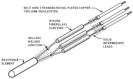
Intermediate leadwires are often used due to the length of the sensor assembly or the temperature profile exceeding the capabilities of the external leadwire (see Figure 5). Intermediate leadwires are usually solid as opposed to stranded for external wires. Solid wires are chosen because they are easier to handle, and are not subject to flexing. Common materials used for intermediate leads are: nickel, copper, constantan, nickel-plated or clad copper (most common), stainless steel clad copper, or platinum. The intermediate leadwires are then insulated with ceramic tubing, fiberglass sleeving, or organic sleeving if the temperature permits. External leadwires may be specified by the customer, but are usually stranded, plated copper conductors insulated with Teflon or fiberglass.
 |
| Figure 5. Intermediate lead wires in a sensor assembly are typically solid wire and are welded to the element leads.
Sensor elements must be packaged to interface with other hardware and to withstand service conditions. |
The subassembly must then be placed into a protective housing (shown as a tubular sheath in Figure 6). This housing is designed to physically mate with the process and protect the subassembly. After being placed into the sheath, the subassembly is packed with a fine grit metal oxide powder, typically aluminum oxide or magnesium oxide. This acts as an electrical insulator while increasing thermal conductivity between the sensing element and the process. The powder also supports the subassembly and protects against damage from mechanical vibration or shock.
These oxides are hygroscopic and must be protected from the environment, particularly in humid areas. If the powder is allowed to absorb moisture, a high-impedance parallel shunt across the sensing element will result and produce a low erroneous output.
Sealing RTD assemblies is one of the biggest problems faced by manufacturers today. Most industrial sensors are sealed with epoxy potting compounds poured into the open end of the sheath. A satisfactory seal can be achieved if adequate attention is given to the proper cleaning and preparation of the surfaces, proper mixing and curing of the compound, and the penetration of potting to a reasonable depth. (See Figure 6).
Ceramic cement is another sealant for assemblies with service temperatures higher than the recommended range for epoxy. The cement is usually impregnated with a silicone fluid for moisture resistance. A more secure but also more expensive method for sealing an assembly is a glass-to-metal or a ceramic-to-metal seat, accomplished by welding a header or connector to the sensor housing.
|


