Application Note PA-HFS
_
_

There are many instances where it is desirable to measure heat flow instead of or in addition to temperature. The use of Micro-Foil® heat flow sensors simplifies the measurement of heat flow wherever accurate data on heating or cooling rates is required. This discussion will focus on the Micro-Foil® type sensors. The unique construction of Micro-Foil® sensors provides an easy-to-attach surface sensor with the lowest thermal capacity, fastest response time and least disturbance to heat flow. Typical applications for heat flow sensors exist in industries such as plastic, machinery, paper and automotive and they are also used in heat transfer studies such as determining the thermal properties of insulation systems. Heat flow sensors are also being used in energy management of buildings. These unique sensors have been used on every major space program, providing accurate data on structural heat transfer, heat shield performance, ablation studies, and aerodynamic wind tunnel studies.

Construction &
Principles of Operation

The Micro-Foil® heat flow sensor is a differential thermocouple type sensor which utilizes a thin foil type thermopile bonded to both sides of a known thermal barrier as shown in Figure 1. The difference in temperature (DT) across the thermal barrier is proportional to heat flow through the sensor. Thermoelectric junctions are formed from materials “A” and “B” on the upper surface of the barrier. In series with these are corresponding junctions mirror imaged on the lower surface. This construction results in an equal number of junctions on the upper and lower surfaces. The two output leads are of the same material, with one coming from the first junction on the upper surface and the other from the last junction on the lower surface.
 In actuality, only one pair of junctions is required for a completed sensor; however the output signal and sensitivity are directly proportional to the number of paired junctions.


Each pair of upper and lower junctions forms a differential thermocouple with voltage output proportional to a small DT. Multiple pairs of junctions in series are used to increase signal and resolution. This assembly is called an in-depth thermopile because heat flows in series through a barrier from hot to cold junctions.
 The output signal represents local heat transfer where the sensor is mounted. The sensor is placed in intimate contact with the surface or body for which heat transfer rates are desired. The same energy must pass through the sensor as is associated with the surface to which it is attached. Any time thermal energy passes through a material — in this case the thermal barrier — a temperature gradient DT is generated. This gradient is directly proportional to the magnitude of the thermal energy flowing through the barrier—the heat transfer rate.
 The factors that effect the magnitude DT are the heat transfer rate (Q), thickness of the barrier (S), and the thermal conductivity (K) of the barrier material. The following simplified expression is given showing the relationship between these factors:

(1)  
The characteristic 63% response time for a Micro-Foil® sensor is approximated by:

(2) t = response time
r = density
Cp = specific heat
K = thermal conductivity
X = cover layer factor
A = 1.2 (thick S) to 2 (thin S)

 Thin sensors provide both fast response and straight-thru heat flow.
 - 1 - 

Thermal Applications

Regardless of application, the primary function of the heat flow sensor is to obtain, as accurately as possible, a direct indication of the thermal energy transfer per unit time per unit area. In the majority of the cases, this is expressed in units of Btu–ft–-2-h–1. In all instances, the heat flow measured will be the thermal energy resulting from conductive heat transfer, or combinations of the following heat transfer modes. Therefore, a discussion of each mode of heat transfer follows:

Conductive Heat Transfer

For measurement of conductive heat transfer, whether it be in insulating materials, existing structures or in complex laminated materials, the main consideration is that introduction of the heat flow sensor must have negligible effects on the process of heat conduction. The best method for insuring intimate contact of the sensor with the test structure is: if it can be, in effect, cast within the material.
 Obviously, this results in a permanent installation and offers the best results. There will be many cases when the integral installation technique is not possible. In these cases, the sensor may be bonded to the inner or outer surface of the material or structure being tested. This measurement technique is based on the fact that the thermal energy conducted through the material must also pass through the sensor before being dissipated into the surrounding environment.

Convective Heat Transfer

Convective heat transfer is often closely associated with conductive heat transfer, since thermal energy conducted through enclosure walls may be transferred throughout the enclosed volume by convection. Installation criteria for convective applications are therefore analogous to those of conductive applications where the sensor is attached to the inner or outer surfaces of the walls or structural materials. One exception, although rarely occurring in everyday testing, is that in high velocity flow regions, the existing airflow may be laminar in nature. Attachment of a sensor directly on a surface in laminar flow may result in disturbances of the flow, culminating in turbulent airflow; precautions should be taken to avoid this. The usual technique is to recess the sensor an amount equal to its thickness, thus making the installation flush with the surrounding area.
 It should be emphasized that it is a rare case where high velocity airflow is found with regard to day–to–day testing. Cases where this is a very important consideration are in applications such as the aerospace industry for airborne testing, wind tunnel testing, etc.


Radiant heat transfer

Measurement of absorbed radiant energy has only one prime requisite, which is: the sensor must have the same absorption or reflection qualities as the surface under test.  One fortunate factor in general testing is that since there is no perfect reflector or perfect absorber, most materials other than clean, smooth metals fall in an emissivity or absorptivity range of 0.4 to 0.8. 
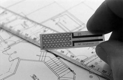
Typical Micro-Foil® heat flow sensors have a nominal emissivity of 0.7. The standard sensor is a good match for a large number of materials.
 For more critical applications such as may be encountered when selecting coatings for walls, siding, etc., the sensor may be coated with the same material that the structure is coated with after bonding to the surface and thereby providing an identical emissivity and absorptivity as the area under test.
 Best results are obtained with a black coating over everything because high absorbitivity is the most reproducible and stable. A permanent black surface is a new option on RdF Micro-Foil® heat flow sensors.

Mounting Considerations

For accurate measurements, the chosen mounting method needs to provide a bond line free of visible voids. Thin bonds maximize respone. Continuous thin bonds are achieved by any of the following methods.
 The ease of installation of the Micro-Foil® sensors makes their applications almost unlimited. The thin and flexible sensors can be attached to flat or curved surfaces and may be permanently bonded in place with conventional adhesives or epoxies. A convenient method for continued re-use at numerous locations is their installation using double adhesive-backed mylar tape. Upon installation, simply connect the leads to a millivoltmeter or similar readout device and a direct measurement of the surface heating or cooling rate in Btu–ft–-2-h–1 or equivalent units is provided.
 For a single use temporary installation, Micro-Foil® heat flow sensors may be ordered with optional pressure sensitive adhesive (PSI) on the mounting surface. The adhesive layer is protected with a release sheet which is removed for use.
 There are other cases where heat flow data is required over a long or extended period. The best method of insuring stable installation for the entire period is to provide a permanent installation. Each user may have his own preference as to an adhesive for mounting the sensor. A few recommendations which have been found satisfactory for past applications are as follows: for attachment to very smooth surfaces much as metallic, plastic or glass surfaces, cements such as Eastman No. 910 have been very satisfactory. For roughened surfaces such as walls, liquid epoxy, or a fast setting RTV are useable to temperatures as high as 250°F. This type of epoxy also has the advantage of curing at room temperature. For the few instances where a high temperature epoxy is desired, Emerson-Cuming No. 104 is useable to in excess of 450°F. However, the use of this adhesive requires an elevated temperature cure such as in an oven or use of radiant heat lamps.

 - 2 -
©2003 RdF Corporation • 23 Elm Avenue, Hudson, NH 03051-0490 USA • TEL 603-882-5195 • 800-445-8367 • FAX 603-882-6925 • www.rdfcorp.com

Instrumentation

Since Micro-Foil® heat flow sensors are self-generating devices that yield an output signal in millivolts or microvolts (depending on sensitivity and range), commonly available readout instrumentation, that can resolve these signals, is all that is required by the user.
  Temperature should be determined at the time the heat flow measurement is made. Apply the available temperature correction to readings at temperatures below freezing. The correction for warm temperatures <110ÁF can normally be neglected. See Figure 4. In many applications, foil type or fine-wire thermocouples built directly into a Micro-Foil® heat flow sensor provide accurate temperature measurement at the best location.
 A heat flow measurement installation, shown in Figure 2, illustrates possible specialized display instrumentation that today is provided by instrumentation system logic functions.

Calibration,
Specifications & Accuracy

The primary calibration function of heat flow sensors is performed using an adiabatic calorimeter. The calibration sensor is carefully mounted on a copper calorimeter slug and a flat black coating is applied to all sensor surfaces for uniform absorptance. The calorimeter slug is then exposed to a radiant heat source on one surface at various power levels. A schematic of radiant heat flux facility is shown in Figure 3.
 For production calibration, a comparison calibration setup is used whereby a test sensor is compared in heat flow series conduction with a primary standard sensor that has been radiation calibrated as described above. The production calibration is performed at 70°F and temperature correction data is provided over the operating temperature range. A typical temperature correction chart for Micro-Foil® heat flow sensors with a Kapton® thermal barrier is shown in Figure 4.
 Both radiation and conduction were used in the methods of calibrations described above. A recent NIST study has confirmed that the resultes apply accurately in convection heat flow as well. RdF’s thin sensor results in the reference (see page 4) were much better than results on thick sensors by others.
 Because of their extremely thin construction, Micro-Foil® sensors feature true isothermal properties where thermal losses are kept to a minimum and highly accurate readings are obtainable. The sensors provide self-


generated millivolt or microvolt outputs, which are proportional to the heat flow through the sensor thickness. Catalog choices of sensitivity are offered by changing the thickness of the thermal barrier and/or the number of thermopile junctions within the sensor.

Typical specifications are as follows:

Heat flow range: Up to 30,000 Btu–ft–-2-h–1.
For heat flow above 3000 Btu–ft–-2-h–1 The installation must prevent overheat. (New water cooled model 27650 is a laboratory grade instrument continuously useable to over 100,000 Btu–ft–-2-h–1 with 2x overrange capability, fast 0.02 second response time and a permanently black sensing surface.)

Typical sensitivity: 0.07 to 40 MV-Btu–ft–-2-sec–1
Typical response time: 0.02 to 0.50 secs. (function of matrix material thickness)
Operating temperature range:
-300 to +500°F
(determined by matrix material and assembly)
Typical thermal impedance:
0.003 to 0.015 Btu–ft–-2-h–1
(determined by properties of matrix material and thickness)
Typical thermal capacitance:
0.01 to 0.05 Btu–ft–-2-°F–1

The use of the calibration procedures described provides sensors with a typical absolute calibration accuracy of 3 to 5%. Reproducibility is in the order of 1%. The construction of the sensor provides infinite resolution over the heat flow range.

 - 3 - 


Summary

Micro-Foil® heat flow sensors are simple devices that can be used to measure heat flow in discrete locations. The sensors are unique because they are very thin and flexible to conform on flat or curved surfaces and provide minimal thermal perturbations to the heat flow. Installation is easy using conventional adhesives or joint filler to   establish thermal coupling for good accuracy.
They require no special wiring, reference junctions, or special signal conditioning. Applications for this unconventional measurement are continuously expanding along with the ability of control systems to utilize the performance information provided.

Reference:

Holmberg, D. G., Womeldorf, C. A., 1999, “Performance and Modeling of Heat Flux Sensors in Different Environments” HTD-Vol. 364-4, Proceedings of the ASME Heat Transfer Division - 1999 Vol. 4, pp. 71-77.

Copyright RdF, 2003, NEW TEXT AND TITLE
Originally published as: "A SIMPLIFIED APPROACH TO HEAT FLOW MEASUREMENT" ISA 1983 0-87664-6/83/1449-8