Application Note AN-S
_
I. Introduction III. Surface Sensor Selection Guide
A. Thermocouple Sensors or RTD Sensors IV. Mounting Considerations
B. RTD Surface Sensors A. Flexible Sensors
C. Thermocouple Surface Sensors B. Rigid Sensors
II. Types of Surface Sensors C. Strapon® Sensors
A. Flexible Platinum Wire RTD V. Typical Applications
B. Flexible Strapon® Thermocouples VI. Surface Thermocouple Specifications
C. High Temperature Thermocouples “Foil” VII. Temperature Resistance Ratio
D. Surface Platinum RTD Capsules Characterstics
E. Heavy Duty RTD's and Thermocouples VIII. Useful Conversions
F. Strapon® RTD's and Thermocouples
_


I. Introduction


Surface temperature is a highly desired but difficult measurement. Unlike applications in which transducers in protective tubes are immersed in fluids under controlled or known circumstances, surface measurements require that sensors be outside of vessels where environmental conditions may affect results. In addition, factors such as conformance with surface contours and thermal as well as electrical paths between the sensors and the objects of measurement influence output signal integrity. Selection of sensors and mounting techniques influence measurement system performance. Surface temperature is of direct interest in many applications and is of value for assessing conditions at inaccessible locations in others. Various sensors and mounting techniques are available. Selection criteria include factors appropriate for any temperature measurements such as range, accuracy, ruggedness, and sensitivity to substances likely to contact the element. Additional considerations peculiar to surface applications include the thickness and flexibility of the units as well as heat exchanged with the object of measurement and the surroundings.

The two most important rules in the use of a surface sensor are:
1) The surface sensor must be mounted in a manner which permits maximum thermal contact and minimal mechanical strain. RdF Designs are easy to mount properly.
2) The surface sensor must be insulated or isolated to make its temperature as close to that of the surface as possible. This is controlled by the user.

To illustrate these points Figure I shows a typical surface sensor installation. The sensor in this case is mounted on a pipe which is carrying a fluid. The point closest to the fluid where a sensor can be mounted practically is the outer wall of the pipe. If the fluid flow is adequate and the temperature fluctuations are not severe, the outer wall temperature will be very close to that of the fluid.

 
 - 1 - 

The surface sensor is only able to measure its own temperature and an attempt must be made to make the surface and sensor temperatures the same. This can be done by placing insulation over the sensor to reduce the effects of the environment and by choosing a mounting method that provides good thermal contact between surface and sensor.

The method chosen for mounting the sensor is equally important. While good thermal contact is desired, a large mismatch in thermal expansion coefficients may cause strain in a wire Resistance Temperature Detector sensor. This strain will produce a change in resistance that could be misinterpreted as a temperature change. Most RdF flexible models use miniature supported thin film sensing elements which eliminate strain effects in surface mounted RTDs.

When mounting both resistance and thermocouple sensors, the leads should be in contact with the sensing surface for some length to reduce the effects of thermal conduction from the sensing wire or junction.

As can be seen by this introduction, an accurate surface temperature measurement is not a simple matter. A review of the application and a procedure for installation should be considered prior to ordering. It is our intention in these application notes to provide general guide lines for the use of surface sensors.


A. Thermocouple Sensors or RTD Sensors?

A review of the various sensor types and tables of specifications will clearly identify the most significant differences between RTD and Thermocouple sensing types. In some applications such as those involving temporary, non-critical measurements at medium temperatures, either type would suffice as only cost would be the determining factor. In general, though, thermocouples have a wider operating range, faster speed of response and are somewhat lower in cost. RTDs, on the other hand, offer higher accuracy and long term stability. Should any question of choice arise, the RdF Sales Department will be pleased to offer their recommendations for specific applications.

B. RTD (Resistance Temperature Detectors) Surface Sensors

° Higher Accuracy
° Long Term Stability
° Higher Signal Output
° No Reference Points or Compensation Circuits needed
° –200°C (–320°F) to 480°C (900°F) Operating Temperature

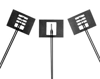
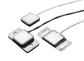
The RTD surface temperature sensors consist of a fine resistance wire or supported thin film sensing grid sandwiched within a wafer-thin insulating carrier and with convenient wire or ribbon lead termination. Most of these sensors are designed to be cemented in place on the surface to be measured. However, RdF also offers a silicone rubber overmold version which is usually attached with a band clamp or tape.

RTD sensors, unlike thermocouples, do not require a reference point, ice baths or temperature compensation circuits. The sensors have a very low thermal mass thereby providing true surface temperature measurements as well as response times as fast as 50 milliseconds. The established position of the platinum sensor as a precision temperature measuring sensor is demonstrated by its selection to define the International Temperature Scale (ITS–90) from –190°C to +660°C. The major reasons for selecting the platinum thermometer as the primary standard are: exceptional stability and repeatability of its resistance temperature parameter. RTDs have a signal output of 50 to 200 times that of a thermocouple. This means that temperature measurements can often be made with standard instrumentation.

_

C. Thermocouple Surface Sensors

° Very Fast Response
° Wide Operating Range
° Low Cost
° Rugged Construction
° Very Easy to Use

These RdF surface thermocouple sensors are available in wire or foil types. As the thermocouples are not a resistance device using a grid wire or thin film as in the RTD type surface sensors, they are considerably more rugged for general purpose use and not affected by strain due to mounting materials or methods. They are inherently simple in design which leads to their lower cost. All thermocouple surface sensors are characterized by their ability to function at considerably higher temperatures than RTD sensors and their faster time response. However, the thermocouple sensor generates a low voltage signal which may require accessory amplification which may prove disadvantageous in a high electrical noise environment.


II. Types of Surface Sensors

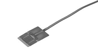
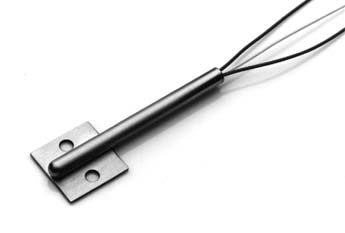
A. Flexible Platinum Stikon® RTD Sensor
     Model 22810

This model is a platinum wire resistance temperature sensor which is designed to be easily installed and can conform to various surface contours. The standard resistance is 100Ω with a nominal IEC 751 curve (.00385Ω/Ω/°C). This sensor's useful temperature range is –200°C to +232°C (–320°F to +450°F).
See Data Sheet R-STK

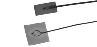
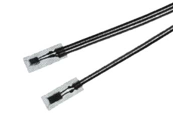
B. Flexible Stikon® Thermocouples

This series of flexible, inexpensive, insulated thermocouples are available in standard type "K", "T", "E", or "J" calibrations. They are easy to install on various surface contours and are usable from –200°C to +260°C (–320°F to +500°F) continuous and to +371°C (+700°F) for short periods.
Request Data Sheet T-STK

 - 2 -
©2003 RdF Corporation • 23 Elm Avenue, Hudson, NH 03051-0490 USA • TEL 603-882-5195 • 800-445-8367 • FAX 603-882-6925 • www.rdfcorp.com

C. Flexible Foil Thermocouples

This series of flexible, fast response thermocouples are available in insulated or uninsulated configurations. They are constructed of thermocouple materials with “K”, “E”, or “T” calibrations. They have useful temperature ranges between –200°C to +816°C (–320°F to +1500°F) depending on the thermocouple type.
See Data Sheet T-F

D. Surface Platinum RTD Capsules

These platinum RTD Capsule assemblies are ideal for the most demanding surface measurement applications. Available in 100Ω or 1000Ω configurations, these versatile components cover the range from –200°C to +260°C (–320°F to +500°F).Available in two, three or four lead wire configurations.
See Data Sheet R-SCAP, R-MINI, R-IMM


_

E. Heavy Duty Sensors Models 22802
     & 26881

These sensors are designed to be used for applications where they may be subjected to harsh environments or physical abuse. They are available as either RTD's or thermocouples and can be mounted by bolting, clamping, welding, etc. They have useful temperature ranges between –200°C to +760°C (–320°F to +1400°F) depending on type and term of use.
See Data Sheet R-HD for RTDs
or T-HD for Thermocouple Types

F. Strapon® Sensors RTD
    Models 22391, 22392, & 22393
    TC Models 26391, 26392 & 26393

These sensors are designed for very easy installation with thermal insulation already installed. They are extremely flexible, available as an RTD or Thermocouple. They have a useful temperature range between –200°C to +232°C (–320°F to +450°F) continuous as mounted, 260°C (500°F) short term clamped.
See Data Sheet R-STR-LOW for RTDs
or T-STR-LOW for Thermocouple Type

 - 3 - 

III. Surface Sensor Selection Guide
 Sensor Style Model  Temperature Range Sensor Type Sensor Size (in.) Carrier Material
 Flexible Wire Strapon® RTD
 22810
 –200°C to +232°C
 (–320°F to 450°F)
Resistance 100 Ω
Platinum @ 0°C
1.00 x 0.62
Polyimide
 Flexible Stikon® TC
 Sensor
 –200°C to +260°C
 Short Term to 371°C (700°F)
Thermocouple
Types K, E, T or J*
0.32 x 0.75
Polyimide/Glass
 Flexible Foil TC
 Sensors
 –200°C to 816°C
 (–320°F to 1500°F)
Thermocouple
Types K, E, or T*
Grounded or Ungrounded
1.00 x 0.75 or
0.37 x 0.75
Optional Polyimide

 Heavy Duty Surface Mount  RTD 22802
 –200°C to 480°C
 (–320°F to 900°F)
Resistance 100 Ω
Platinum @0°C
1.00 x 1.00

316 Stainless Steel
-
-
 Heavy Duty Surface Mount  TC 26881
 –200°C to +760°C
 (–320°F to +1400°F)
 Leads to 480°C (900°F)
Thermocouple
Types K, E, T or J*
Grounded or Ungrounded
1.00 x 1.00

316 Stainless Steel

 Strapon® RTD Sensors  22391, 22392
 & 22393
 –200°C to +232°C as mounted,
 +260°C (500°F)
 short term clamped
Resistance 100 Ω
or 1000 Ω
Platinum @0°C

1.00 x 1.00


Stainless Steel
overmolded with medium density polymide pad
-
 Strapon® TC Sensors  26391, 26392
 & 22393
 –200°C to 232°C continuous
 as mounted, 260°C (500°F)
 short term clamped
Thermocouple
Types K, E, T or J*
Grounded or Ungrounded
1.00 x 1.00

Stainless Steel
overmolded with medium density polymide pad
 Miniature Flexible
 Platinum RTDs
 29222, 29223
 –200°C to 260°C
 (–320°F to 500°F)
Thermocouple
Types K, E, T or J*
Grounded or Ungrounded
0.14 x 0.40 or
0.19 x 0.40
Polyimide

 Surface Platinum RTD
 Capsules
 29230, 29309
 –200°C to 260°C
 (–320°F to 500°F)
Resistance 100 Ω
or 1000 Ω
Platinum @0°C
0.22 x 0.50 or
0.30 x 0.50
Polyimide

 Immersible Surface
 Platinum RTDs
 29272

 29280


 –200°C to +232°C
 (–320°F to +450°F)
 –200°C to260°C
 (–320°F to +500°F)
Resistance 100 Ω
or 1000 Ω
Platinum @0°C


0.30 x 0.80

0.25 x 0.50 or
0.30 x 0.50
Polymide


*K–Chromel/Alumel, E–Chromel/Constantan, T–Copper/Constantan, J–Iron/Constantan

IV. Mounting Considerations

A. Flexible Sensors

The first step in installing a surface sensor is the determination of the mounting method. In the case of some sensors, mechanical mounting hardware is available and these will be described later, but in most cases an adhesive is required. In selecting an adhesive the following questions should be considered:
• Is the expected operating temperature range compatible with the adhesive under consideration?
• Are the coefficients of thermal expansion of sensor, surface and adhesive similar?
• Is the adhesive application compatible with the installation? eg. if the adhesive requires a cure at an elevated temperature, it may become a problem in a remote installation.
• Is the adhesive mounting intended for permanent or temporary installation?

There are several types of adhesives that are commonly used to mount sensors:
1) Epoxies
This type adhesive is available in a variety of forms including liquid, pastes, films, tapes and powders, but are usually found in two parts which must be mixed before applying.


Cure times vary between 5 minutes at room temperature to several hours at elevated temperatures. Most epoxies have fillers added to the basic resin which make them ideal to fill gaps or over coat sensors.

2) Cyanoacrylate Adhesives
These adhesives are of the “super quick set” variety. They cure at room temperature in 10 to 60 seconds. There are temperature and humidity restrictions for their use. Because most cyanoacrylates either do not contain fillers or have limited capability to fill voids, parts must be in close contact.

3) Silicone
Silicone adhesives have the advantage of being rubbery and provide a resilient low stress bond between sensor and surface. They are available in single or two part paste or even as a double sided tape which can be instantly applied to sensor and surface. They have a very wide useful temperature range. The paste type silicones require a long cure time and are subject to possible reversion if not cured above the required service temperature.

4) Polyimide Adhesives
There are several families of polymer adhesives which provide excellent adhesion and high temperature stability. However, they must be cured under carefully controlled temperature and pressure requirements. This makes field installation very difficult.

 - 4 -
©2003 RdF Corporation • 23 Elm Avenue, Hudson, NH 03051-0490 USA • TEL 603-882-5195 • 800-445-8367 • FAX 603-882-6925 • www.rdfcorp.com

III. Surface Sensor Selection Guide
Leads Typical Applications  Data Sheet
#26 AWG Stranded, Teflon® Insulated Ribbon cable Flat or curved surfaces such as plastic, metal or glass for industrial, laboratory, commercial or aerospace applications.  R-STK
#30 AWG Solid, PFA or
Fiberglass Insulated
Flat or curved surfaces such as plastic, metal or glass for industrial, laboratory, commercial or aerospace applications.  T-STK
0.001 x 0.03 T/C Ribbons or
#30 AWG Solid, Fiberglass Insulated
Extremely low mass sensor for precise analytical or experimental measurements –
fast response time.
+
 T-F
#22 AWG Stranded, Teflon® or
Fiberglass Insulated
Heavy duty applications where the sensor can be mechanically mounted such as
boiler tubes, flue stacks, refineries or plant applications where physical abuse is common. Bolt-on flange can also be welded or bonded.
 R-HD
#22 AWG Stranded T/C Conductors, Fiberglass Insulated Heavy duty high temperature applications where the sensor can be mechanically mounted such as boiler tubes, flue stacks, refineries or plant applications where physical abuse is common. Bolt-on Flange can be welded.  T-HD
2 wire: 22 AWG, FEP, Twisted Cable
3 wire: 24 AWG, FEP, Twisted Cable
4 wire: 26 AWG, PFA, Ribbon Cable
Stranded, Teflon® Insulated Cable
Flexible sensors for immediate installation for permanent or temporary measurements
of fluid lines for energy management systems, process plants, refineries, utilities or aerospace applications. Suitable for condensing or wet environments.
 R-STR-LOW
#20 AWG Stranded, Fiberglass Insulated w/Fiberglass Overbraid
+
Flexible sensors for immediate installation for permanent or temporary measurements
of fluid lines for energy management systems, process plants, refineries, utilities or aerospace applications.
 T-STR-LOW
#28 AWG Stranded,PFA Teflon®
IInsulated Ribbon Cable
Flat or curved surfaces such as plastic, metal or glass for industrial, laboratory, commercial or
aerospace applications.
 R-MINI
#28 AWG Stranded, PFA Teflon®
Insulated Ribbon Cable
Flat or curved surfaces such as plastic, metal or glass for industrial, laboratory, commercial or
aerospace applications.
 R-SCAP
Stranded lead cables;

#22/#24 AWG, FEP Teflon®
Twisted
#26 AWG Stranded, PFA Teflon®
Ribbon

Flat or curved surfaces such as plastic, metal or glass for industrial, laboratory, commercial or
aerospace applications where condensation or shallow immersion occurs.


 R-IMM

*K–Chromel/Alumel, E–Chromel/Constantan, T–Copper/Constantan, J–Iron/Constantan

5) Ceramic Adhesives
Ceramic adhesives or cements have the advantage of having the highest useful temperature. They are used in paste form with metal oxides used as fillers with an acid used as the binder. They often require a cure at elevated temperatures. After curing, ceramic cements are generally hard, brittle and hygroscopic.

6) Solvent Release Adhesives
There are a number of commonly available inexpensive adhesives which require the release of a solvent from the resin material to form the bond. It should be noted that if the sensor is impervious to the solvent, the adhesive will not cure properly. Caution should be used in selecting these adhesives. After the adhesive has been selected a procedure must be developed which can be used to consistently mount the sensor The following is a general guideline for a typical mounting procedure.

7) Surface Preparation (Figure 2)
One of the most important steps in mounting a surface sensor is the proper preparation of both the sensor and mounting surfaces. Dirt, grit, oils, finger prints, etc. can act as a mold release, and affect the adhesion of the sensor to the surface. As a minimum, the sensor and surface should be solvent cleaned with a clean cloth wetted with alcohol, acetone, M MEK or toluol.


_

Caution: some surfaces may be adversely affected by some solvents and a pretest of the solvent on the surface is recommended. In the case of metal or shiny hard surfaces roughening of the finish is usually required to insure a better bond. This can be done by roughening the surface with a light sandblasting or manually applied abrasive. Clean air should be used to remove grit after roughening is complete, followed by a solvent cleaning as described above.

 - 5 - 

8) Adhesive Preparation
After selecting the adhesive the manufacturers instructions should be carefully reviewed. Particular note should be made of mixing ratios, curing instructions and storage life. If there is a possibility that the manufacturers instructional limitations may be exceeded, the manufacturer should be consulted for his comments or recommendations. When developing the installation procedure the manufacturers limits or tolerances should be used.

9) Installation (Figures 3 & 4)
The sensor first should be held in the area it is to be installed to check for any size or contour problems. A method for anchoring the leadwires to provide strain relief and thermal heatsinking should be determined. When all of the pre-installation preparation is complete, apply adhesive to both sensor and surface and push sensor into place to squeeze out excess adhesive. A thin glue line will produce better temperature measurement results than a thick glue line. If a flexible sensor is mounted to a curved surface, the resistance winding should be transverse to the curvature to reduce strain effects. Pressure should be applied to the sensor during the cure to assure that the entire sensor is bonded to the surface contour. Pressure can be applied using a rubber pad clamped over the sensor. The rubber's resiliency will provide equal pressure on the sensor. A mold release or Teflon® coating should be used on the pad to prevent the adhesive from bonding to the rubber.

10) Electrical Check
Once the adhesive is cured the clamps must be removed, insulation should be placed over the sensor and lead wires connected to instrumentation leads. At this point an electrical continuity test should be performed with a VOM. If the sensor is a RTD an estimated resistance value can be found in the resistance versus temperature table. In the case of a thermocouple sensor, a voltmeter can be attached to the leads and by applying heat to the sensing area a signal will be generated that will confirm the integrity of the sensor and identify the polarity of the wires. When the mounting surface is electrically conductive a check to detect shorting between sensor and surface should be performed by checking continuity between surface and sensor leads. In the case of a grounded thermocouple this should be a dead short, for all other sensors this should be a minimum of 1 megohm on a VOM.

B. Rigid Sensors

Sensors with rigid metal cases can also be bonded on a surface but are more often mounted by a more mechanical method such as welding,

_

brazing, bolting or clamping. The purpose of the rigid sensor is to provide a rugged sensor for a harsh environment so any of the forementioned mounting techniques will not damage the sensor except for extreme overheating during brazing or welding. The most common cause of damage to these sensors is due to inadequate strain relief for the lead wire. In areas where they are subject to abrasion or other mechanical abuse a cable with stainless steel overbraid or an armored jacket is recommended. After installation, an electrical check as described in the previous section should be performed.

C. Strapon® Sensors

The Strapon® sensors are manufactured with the sensor attached to a contact shim and then overmolded with an insulating layer ready to be clamped to the surface. The Strapon® sensor can be purchased without hardware (Models 26391 & 22391) for those who wish to add their own clamp or mount them by cementing, or even taping them to a surface. Another style (Models 26392 & 22392) have a mounting shim which allows the sensor to be bolted to a surface. In both cases when installing a Strapon® style sensor, the sensor should be tightened until the shim is firmly on the surface, but not tight enough to strain the sensing element or deform the silicone rubber. A thermal grease can be used between the surface and sensing shim to increase the thermal conductivity if desired, but it should be noted that some silicone heat sink compounds could have an adverse effect on the silicone overmold. Strapon® Models 22393 and 26393 have an adapter and pipe clamp to facilitate installation. The adapter has a built-in stop to prevent excessive tightening of the clamp.

V. Typical Applications

1. Biological Sensor (Figure 5)

Biological samples are often frozen for future use. A few examples are:

The freezing of cancer cells for future research.
The freezing of skin tissue removed from cadavers for grafts on burn patients.
The freezing of animal sperm for future insemination and special breeding.

Living tissue is primarily water and as it freezes the water will expand, causing friction in the cells and possibly destroying the specimen. For this reason it is extremely important to carefully control the freezing rate. An RdF Stikon® thermocouple can be used for this application. A Type “T” thermocouple is chosen because it has published limits of error below 0°C. It is attached to the specimen container and is immersed into a cooling solution. Due to the low thermal mass of the thermocouple bead it can accurately follow the cooling process of the specimen. After the temperature of the sample is stabilized it can be moved to a storage area and the thermocouple can be removed for use on another container. In this case a pressure sensitive silicone adhesive can be used easily.

 - 6 -
©2003 RdF Corporation • 23 Elm Avenue, Hudson, NH 03051-0490 USA • TEL 603-882-5195 • 800-445-8367 • FAX 603-882-6925 • www.rdfcorp.com

2. Mold Temperature Sensor (Figure 6)

The manufacturer of molded plastic cases needs to measure temperature inside the mold. This measurement was used to indicate variations in temperature and to control cycle rates which optimize production and reduce rejects. Due to the complex design of the mold, the use of a typical immersion sensor would require major modifications and prove costly. Also, the normal thermal mass of conventional thermocouple sensors prohibits the sensor from indicating true mold temperature. A foil thermocouple can be attached to a wall in the molding cavity and due to its extremely small thermal mass will respond rapidly to any changes. This style sensor is easy to install and the lead wires can be routed between various parts on the mold assembly.

3. Structural Measurements (Figure 7)

The manufacturer of sophisticated military jet aircraft needs to measure many temperatures on various structures during test flights. These measurements will help detect design flaws and optimize performance on prototype aircraft before production begins. The sensor must have a very wide temperature range because temperatures can vary from 500°F near the engines to subzero at the wing tips. The sensor must also have very low mass and not affect the normal function of even extremely small parts.

A polyimide insulated flexible sensor such as RdF Model 22810 is ideal for this type measurement. The polyimide thermally stable material and the sensor with lead wires weighs less than 6 grams. The Teflon® insulated lead wires are easily terminated to connectors or instrumentation. Both Teflon® and polyimide are chemically resistant to most fuels, solvents, hydraulic fluids, cleaning agents and other chemicals used in the aerospace industry. These sensors are also easily installed using conventional epoxy adhesives.

_

4. Boiler Tube Measurements (Figure 8)

Boiler tubes carry high temperature water under extreme pressures. These tubes are generally bundled in tight configurations with little clearance. Due to the fact that flow restrictions affect boiler performance and the lack of clearance between tubes, the best way to obtain a temperature measurement is by an external surface measurement. RdF Sensor Models 22802 or 26881 are ideal for this type of application. The sensing pad can be formed by RdF to mate with the radius of the tubes. The sensor can be clamped or welded to the tube and lead wires can be routed to connection points beyond the tube bundle. These sensors are now a permanent part of the installation and are rugged enough to withstand unintentional abuse during normal maintenance.

5. Energy Management (Figure 9)

With the high cost of today's energy an energy management system has become a necessity for most large facilities. When installing these systems in older buildings, temperature measurements are required on pipes that were installed when the building was originally built. The contractor does not know the material or condition of this piping and is reluctant to do any machining for fear of fractures or failures that would require extensive repair. The Strapon® style sensor, RdF Models 22393 or 26393 equipped with a pipe clamp are ideal for this application. The clamp can be chosen to fit the appropriate pipe size. The sensor can be installed in tight areas by people with no prior training. This easy installation makes it ideal as a permanent measurement or for a temporary measurement for setting up the system.

 - 7 - 

VI. Surface Thermocouple Specifications

_ _ _ _ _ _ _ _ _ _ _ _ _ _ _
TC
 Type 
_  Conductor
 Material
_  20° to 200°C
 Sensitivity

 Avg. µ v/°C
_  ANSI
 Color
Code
_
CONDUCTOR IDENTIFICATION:
_ Max. Long-Term
Temperature
Range, °C**
_  Limits
 of Error
 Standard*
Positive + _ Negative –
_ _ _ _ _ _ _ _ _ _ _ _ _ _ _
J _  Iron/Constantan _ 54
_  White/Red _  Magnetic _  Non-Magnetic _  0 to +320 _  ±2.2°C
 ±0.75%
T _  Copper/Constantan _ 45 _  Blue/Red _  Copper Color
 Non-Magnetic
_  Non-Magnetic  _  -200 to +200 _  ±1°C
 ±0.75% or
±1.5%<0°C
K _  Chromel/Alumel _ 41 _  Yellow/Red _  Non-Magnetic _  Magnetic _  -200 to +480 _  ±2.2°C
 ±0.75% or
 ±2%<0°C
E _  Chromel/Constantan  _ 67 _  Purple/Red  _  Non-Magnetic _  Silver Color
 Non-Magnetic
_  -200 to +370 _  ±1.7°C
 ±0.5% or
 ±1%<0°C
*Limits of error are new material interchangeability expressed in percentage of positive or negative Celsius temperature when greater than basic limit.
**Temperature range is for the small or stranded wires in surface TCs.

VII. Platinum Resistance Ratio Table

Temperature Coefficient 0.00385ohms/ohms/°C — Nominal IEC751 - Class B Interchangeability
°C ±Class B _ R/R0 _ °C ±Class B _ R/R0 _ °C ±Class B _ R/R0
_ -200 _ _ _ 0.185 _ _ _ 50 _ _ _ 1.194 _ _ _ 300 ±1.8 _ _ 2.120 _
_ -190 _ _ 0.228 _ _ 60 ±0.6 _ 1.232 _ _ 310 _ _ 2.156 _
_ -180 ±1.2 _ 0.271 _ _ 70 _ _ 1.271 _ _ 320 _ _ 2.191 _
_ -170 _ _ 0.313 _ _ 80 _ _ 1.309 _ _ 330 _ _ 2.227 _
_ -160 _ _ 0.355 _ _ 90 _ _ 1.347 _ _ 340 ±2.0 _ 2.262 _
_ _ _ _ _ _
_ -150 _ _ 0.397 _ _ 100 ±0.8 _ 1.385 _ _ 350 _ _ 2.297 _
_ -140 ±1.0 _ 0.439 _ _ 110 _ _ 1.423 _ _ 360 _ _ 2.332 _
_ -130 _ _ 0.480 _ _ 120 _ _ 1.461 _ _ 370 _ _ 2.367 _
_ -120 _ _ 0.521 _ _ 130 _ _ 1.498 _ _ 380 ±2.2 _ 2.402 _
_ -110 _ _ 0.562 _ _ 140 ±1.0 _ 1.536 _ _ 390 _ _ 2.436 _
_ _ _ _ _ _
_ -100 ±0.8 _ 0.603 _ _ 150 _ _ 1.573 _ _ 400 _ _ 2.471 _
_ -90 _ _ 0.643 _ _ 160 _ _ 1.610 _ _ 410 _ _ 2.505 _
_ -80 _ _ 0.683 _ _ 170 _ _ 1.648 _ _ 420 ±2.4 _ 2.540 _
_ -70 _ _ 0.723 _ _ 180 ±1.2 _ 1.685 _ _ 430 _ _ 2.574 _
_ -60 ±0.6 _ 0.763 _ _ 190 _ _ 1.722 _ _ 440 _ _ 2.608 _
_ _ _ _ _ _
_ -50 _ _ 0.803 _ _ 200 _ _ 1.759 _ _ 450 _ _ 2.642 _
_ -40 ±0.5 _ 0.843 _ _ 210 _ _ 1.795 _ _ 460 ±2.6 _ 2.676 _
_ -30 _ _ 0.882 _ _ 220 ±1.4 _ 1.832 _ _ 470 _ _ 2.709 _
_ -20 _ _ 0.922 _ _ 230 _ _ 1.868 _ _ 480 _ _ 2.743 _
_ -10 _ _ 0.961 _ _ 240 _ _ 1.905 _ _ 490 _ _ 2.776 _
_ _ _ _ _ _
_ 0 ±0.3 _ 1.000 _ _ 250 _ _ 1.941 _ _ 500 ±2.8 _ 2.810 _
_ 10 _ _ 1.039 _ _ 260 ±1.6 _ 1.977 _ _ 510 _ _ 2.843 _
_ 20 _ _ 1.078 _ _ 270 _ _ 2.013 _ _ 520 _ _ 2.876 _
_ 30 _ _ 1.117 _ _ 280 _ _ 2.049 _ _ 530 _ _ 2.909 _
_ 40 ±0.5 _ 1.155 _ _ 290 _ _ 2.085 _ _ 540 ±3.0 _ 2.942 _
_ _ _ _ _ _ _ _ _ _ _ _ _ _ _ _ _ _
_ _ _ _ _ _ _ _ _ _ _ _ _ _ _ _ _ _ _ _ _ _ _

VIII. Useful Conversions

Temperature:
°C = 5/9 (°F – 32) °F = 9/5 (°C) + 32 °K = °C + 273.15 °R = °F + 459.67
Heat Transfer Coefficient:
Multiply By To Obtain
BTU / (HR) (FT2) (°F) 0.0001356 CAL / (SEC) (CM2) (°C)
_ 1.929 x 10⁻⁶ BTU / (SEC) (IN2) (°F)
_ 0.0005674 WATTS / (CM2) (°C)
Thermal Conductivity:
Multiply By To Obtain
BTU / (HR) (FT2) (°F / FT) 0.00413 CAL / (SEC) (CM2) (°C / CM)
_ 12 BTU / (SEC) (F2) (°F/IN)
_ 0.0173 WATTS / (CM2) (°C / CM)